Reporting Cross Section Point Codes
Updated February 26, 2018
This article applies to:
- RoadEng Civil
- RoadEng Forestry
This example will demonstrate how to display point code information (offset, elevation, coordinates etc.) from surveyed cross sections.
Watch the Tutorial Video on YouTube:
You can access the files referenced in this example HERE.
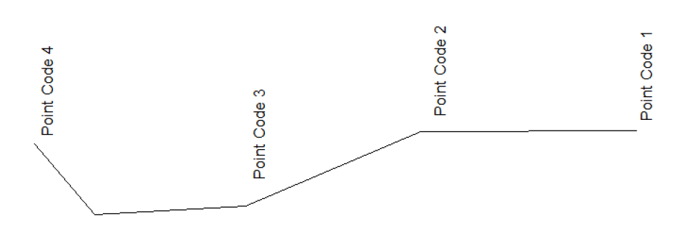
Figure 1: Cross Section Point Codes
Prior to starting this example, a TIN surface which includes the surveyed points should be created. Each of the feature lines created from the survey should be named appropriately. A new Location design should be created using the TIN surface and the centerline feature as the initial alignment.
Creating Reference Features
1. Open the Location module and choose menu File | Open, SurveySections.dsnx.

Figure 2: Survey Sections Location Design.
2. Choose menu Setup | Location Setup. Choose the Alignment tab and click on Features button to activate the Reference Features dialog (as shown below).
3. Click on RF 1 and check “Use as reference feature”. In the Feature group box, click on the Browse button and select “RRELN-11”. Press OK.

Figure 3: Creating a Reference Feature
4. Click on RF 2 and check “Use as reference feature”. In the Feature group box click on the Browse button and select “RRSHR-0”. Press OK.
5. Repeat step 4 and add reference feature for “RRTOE-13”. When complete press OK twice to remain to the main screen.
Setting Up the Cross Section Template
The next step is to assign a XSEC – Cross Section Points template to create template point codes for reporting.
6. From the Home tab choose Templates. Click on + button beside XSEC – Cross Section Points template. Click on the Point codes on surface (beta) – right component. Click on Properties
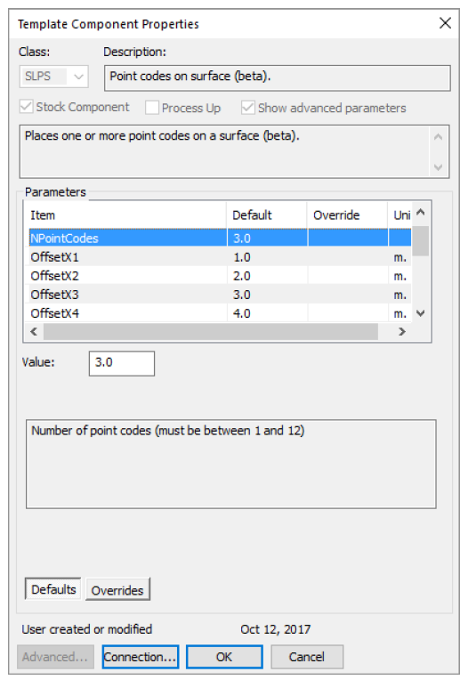
Figure 4: Template Component Properties
NOTE: The Point Codes on Surface Component is available in the standard E-library (Version 8 or higher). It creates template point codes (PC1, PC2, PC3…) on a surface corresponding to fixed offsets or reference features.
7. Set the component properties as follows:
- NPointCodes = 3
- OffsetX1 = Reference Feature 1 (RRELN)
- OffsetX2 = Reference Feature 2 (RRSHR)
- OffsetX3 = Reference Feature 3 (RRTOE)
8. Press OK to return to the main screen. Click on the cross section window icon to view the sections.
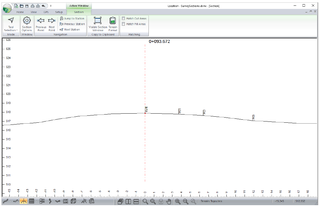
Figure 5: Section View Showing Point Codes.
Creating A Point Code Report
9. Click on the Data Window icon at the bottom of the screen to activate a Data Window.
10. Right click in the Data window and choose Data Option. Click on Columns to activate the Data Window Fields dialog.

Figure 6: Data Window Fields Dialog
11. Add fields L-Stn from the L-line folder. In the Template Codes folder add PC1R-Hoff, PC1R-Elev, PC2R-Hoff, PC2R-Elev, PC3R-Hoff, and PC3R-Elev.
NOTE: PC1R-Hoff corresponds to the horizontal offset for point code PC1. PC2R-Elev corresponds to the elevation for point code PC1
12. Press OK and the Data Window report should appear as shown below.

Figure 7: Offset and Elevation Report
13. File | Close. Do not save changes.