Creating a Profile
Updated December 15, 2021
This article applies to:
- Terrain 3D
- Terrain Forestry
- RoadEng Civil
- RoadEng Forestry
This Knowledge Base article is an excerpt from one of our tutorial files. The files referenced in the article, as well as the full tutorial document, are available in our Tutorial Installer.
Stream Survey Example
This example demonstrates how to create a profile, set scales and display properties.
A profile is created by assigning a fence section feature to a Profile Window. The horizontal axis in the Profile Window is the distance (horizontal) along the fence section feature. The vertical axis is elevation.
Any feature can be a fence section (even closed loops or features which cross themselves). If the fence section consists of two points the profile becomes a standard cross section.
Note: See Getting Started section for file install folders (<Terrain> and <Defaults and Layouts>)
-
 File | Open <Terrain>\Profile\topograph.terx.
You will see the features shown in the figure below.
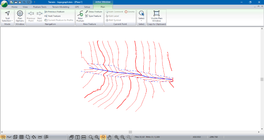
Figure 1: Stream Survey (topograph.terx)
The Terrain feature representing the stream is a three-dimensional polyline that is used to define the surface (and indirectly, to define the contours). In the steps below, you will view this feature in a Profile window.
Create a Profile window using the stream feature as you fence section:
-
Select Stream-2 (the thick blue feature running across the middle) by clicking on it with the selection cursor
 .
. -
View | New Window | Profile from dropdown menu.
-
The new Profile window uses the current feature as the fence section; the feature name is part of the Profile title bar (figure below).
-
View | Tile Vertically (or press from the Status Bar) to show Profile and Plan windows side by side (figure below).
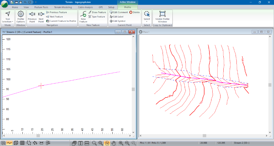
Figure 2: Profile with Stream-2 as Fence
Notice that the Plan and Profile windows both show the stream feature as selected (magenta in color) and both windows show the current point as a red cross. Sometimes it is not obvious how the profile view relates to the plan; the current point can help and there is a shadow cursor displayed in the windows that do not contain the mouse.
-
Using key strokes <Ctrl + N> and <Ctrl + B> move the current point forward and backward on the current feature.
-
Move your mouse around in the Plan window (don’t click any mouse keys!) and watch the shadow cursor
 in the Profile window.
 -
Similarly, move your mouse around in the Profile window and watch the shadow cursor
in the Plan window.
The scale in the Profile is automatic, so the feature fills the window. Use the Profile window options to define an explicit scale with distortion:
-
Right-click the Profile window and select context menu Active Window (Profile) Options….
-
This will open Profile Window Options dialogue box (figure below). Notice the Scale is set to Auto Scale.
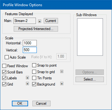
Figure 3: Profile Windows Options Dialogue Box
-
Clear the Auto Scale check box and change the Horizontal and Vertical scales to 1000 and 500 respectively.
-
Notice the other controls in the Profile Windows Options dialogue box; you can change the fence feature (Main) at the top of the dialogue box.
-
Press OK to close the dialogue box.
The Profile Window has a new scale with 2:1 vertical distortion. Now we’ll display some automatic labels in the Profile.
-
Turn on Elevations and Grades labels: Profile | Profile Options to open the Profile Window Options dialogue box (figure above).
-
Push the
 button beside Labels to open the Profile Window Labels dialogue box.
 -
Turn on Elevations and Grades by double-clicking on them in the list-box.
-
Press OK twice to return to the main screen.
The screen should now look like the figure below.
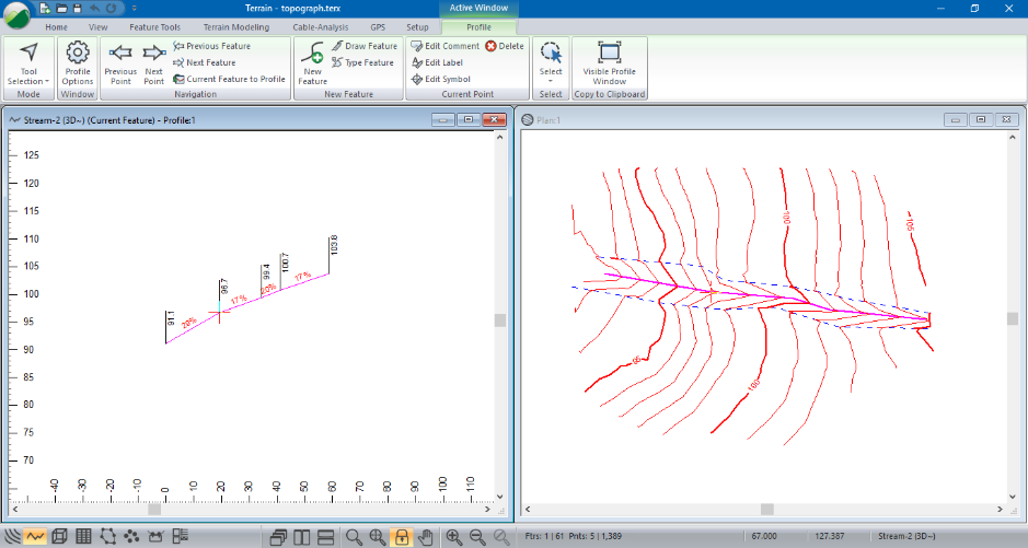
Figure 4: Stream Profile with Elevations and Grades
Reverse the direction of the stream feature:
-
Make sure the stream feature is still selected.
-
Feature Tools | Reverse button.
-
If there is a TIN surface in plan-view a dialogue box: “Warning, existing Terrain Triangles will be cleared”, press OK.
Notice that the labels update automatically. One should note that this reversal does not change the topographic contours and the natural direction of the stream would be such that the V’s in the contour would point to the downgrade direction of flow of the stream.
-
File | New. Do not save the changes.